|
Chapter 7 |
To give you an overview about the structure and the operation of RadioCom we have created a video.
VIDEO coming soon
After successful installation, you will see the RadioCom icon on the the
desktop.![]()
Turn your radio on. Double-click on the icon to start RadioCom. A small
launch window (splash) will appear which shows you the loading status.

If error messages appear, such as ‘Radio Initial Error’ which means that the switchbox was not found or ‘Audio Initial Error’ which means that the audio settings are not correct, you have to follow the initial steps again or have a look at the FAQ.
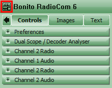
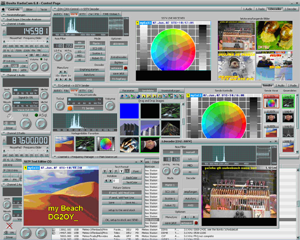
The window ‘RadioCom’ control page will appear.

On the control page receiving and transmitting with your radio are controlled and adjusted. This window has a Left-Control on the left, which can be hidden in the left page with an arrow. In addition, there is a Top-, a Mid- and a Bottom-Control, in which there are various control-dialogue. These windows have a split bar on top for opening and closing. In these split bars, there are buttons, which control a high number of control-dialogues in return with additional tab-buttons for further sub-dialogues.
At first, you will perhaps find it complicated to remember all the appropriate levels. That is why there is the possibility to limit the display to one radio channel (under ‘Preferences’)
For your individual design of the different levels and channels the split-bar buttons can be moved to another split bar by the drag and drop method. If you drop the button right on a split bar, then it will be fixed there. If, however, you drop the button in the middle of the window, then there will be separate control dialogue, which you can move to anywhere you want, even to a second screen. If you close this dialogue, it will be moved back to the original split bar. If either Mid- or Top Control is empty, then ‘Control’ will be shut down and cannot be opened.
Bottom Control cannot be closed, only minimized. However, this window can be covered by another dialogue, which may come from Mid- or Top control. When opened, the split bar of Bottom Control covers the two split bars located above them.
The arrow on the upper left hides Left Control. This way you will get the maximum screen size to work with SatTrack, for example.
Left Control
In Left Control there are mini dialogues for the continuing control of
the radio s and their audio settings. These dialogues will not be
explained here because they only reflect the main dialogues. Here you
will also find the Preferences and the DualScope. The split bars
‘Audio’ and ‘Radio’ can be hidden, when you connect the first radio and
Audio, for example. If you open the DualScope, only the second radio and
audio will appear. If you close the DualScope again, you can look at all
options and open them.
General Operation of the Control Elements
|
There are three main windows: Control Page for controlling the receiver or the transmitter Image Page Image Page for evaluating the received or transmitted picture Text Page evaluating the received or transmitted texts
All pages have split bars which you can click on to
minimize or maximize the options. |
 |
||||||||||||||||
|
Split Bar:
|
|||||||||||||||||
|
When you point with your mouse on windows, a button or on buttons, a hand  appears. That means that special options are available. These
options will be explained later in the manual. Normally, it is
done by a click on the left mouse button or by turning the mouse
wheel. appears. That means that special options are available. These
options will be explained later in the manual. Normally, it is
done by a click on the left mouse button or by turning the mouse
wheel.In the frequency list the
mouse pointer will turn into a hand, if you point at the book
symbol
The mouse pointer will turn into a hand, if you point at the
satellite symbol
|
|||||||||||||||||
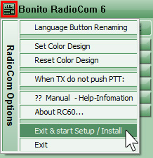
| RadioCom option menu If you click on the icon
*The Entry ‘Language Button
Renaming’ is only intended for translations and is an internal
function which you should disregard. It has not been hidden to
unable translators to change the language. |
|
||||||||||||||||
|
Right mouse button = context menu
Functions of the mouse wheel |
|
|
|
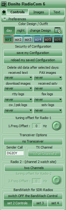
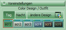
With ‘Preferences’ you can change the ‘Color Design’ or you can change design to your liking with ‘Change Design’. How this works is explained here. Automatic Delete
Feature If you want frequencies to be continuously changed by the same amount, you can set the difference with ‘Tuning Offset’. This difference will be added when it is positive and subtracted when negative. If you do not wish to transmit you can turn off the transmit window by clicking on the button ‘No transceiver’. You turn on this window again with the same button. If you are a ham radio operator, you can enter your call sign under ‚Sender Call‘ . Actually, the transceiver should always be installed on channel 1, but with the button ‚Sender Receiver‘ it can be assigned to channel 2.
In the Radio 2 field, you can determine if you want to
use one or two radios and if a tuning offset has to be used with
radio 2.
Save configuration |
| You can create your own design of the program. You can use the default designs (scr 1-6) or create your own. This feature does not only have an optical aspect. For example, if you work in the dark, a light-colored screen is very hard to look at. Simply change RadioCom to a darker night design. |
|
|
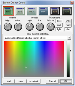
To create your own design, click on ‘Change design’ and the window ‘System Design Colors’ will appear. With different controls you can change the color of the various areas of the window. Screen: Changes the background color. ‘Bright’ means brightness and Satur (?) means the color saturation. Scopes: Changes the scopes, the tuning and the frequency indicators. ‘Bright’ controls the brightness in the background and ‘Line’ the brightness of the lines..
Button flat style: With this button you can vary
the concavity of the buttons. Starting with version 6.3, there
is also a ‘glass style’ which lends a nice glossy touch to the
buttons. |
 |
With the help of the integrated
color management you can design your own user interface, which
facilitates operation at night .


|
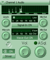
Audio control is located in Left
Control. There you can make all necessary audio settings and choose the
right input again. |
 |
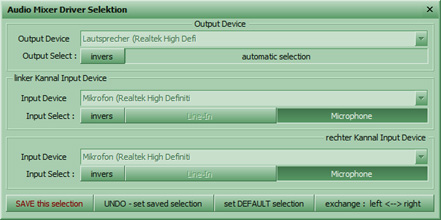
Setting the driver – audio input- Audio Mixer
|
You can check the audio
settings and change from ‘Line-In’ to ‘Microphone’ if necessary.
The Invers button ensures that the soundcard which interpretes
‘turn on’ as ‘turn off’ will get the right command. |
 |
|
Chapter
8 |
![]()
The bottom control is the lower part of the 3 controls and includes: FrequencyManager, ScheduleList, Sattracking and the Bonito SDR-BandWatch.
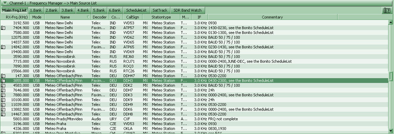
In the Bottom Control you'll find the frequency Manager. It is a great list of frequency in which everything is linked. This list contains all the necessary data for the reception. With a double mouse click the radio station is tuned in on the radio with the correct frequency shift, activate the corresponding decoder and the reception program is started with all parameters and will begin to decode.
Easy frequency selection: When you have chosen a list entry and press the space bar, the frequency of the radio will be switched. This way you can check whether there is any usable reception. However, if you press Enter or double-click on the list entry the frequency will be tuned in, the reception program will be launched and the necessary reception parameters transferred. The reception program is now ready and will start decoding data.
Arranging Fovorites:
There are 7 available lists: „Main-List“ and the 6 Banks. You can
arrange the 6 Banks easily by deleting all radio stations that are not
applicable to your area or you add new entries via the Drag&Drop-Method.
Selecting a Frequency by "grabbing" it and dragging it to one of the
Banks Buttons. The frequency is copied thereby to this Bank. The main
list is maintained by us over the Internet via update. The 6 banks are
for your disposal.
Arranging and Sorting Lists:
![]() If
you point your mouse arrow on the dividing lines between the upper bar
and the list, a cross will appear. If you capture the cross with the
left mouse button and pull to the left or right you can adjust the
display width. Clicking on the list areas „RX-Frq“, „Mode“, „Name“ etc.,
will sort the list respectively. This will help you find a particular
radio station.
If
you point your mouse arrow on the dividing lines between the upper bar
and the list, a cross will appear. If you capture the cross with the
left mouse button and pull to the left or right you can adjust the
display width. Clicking on the list areas „RX-Frq“, „Mode“, „Name“ etc.,
will sort the list respectively. This will help you find a particular
radio station.
The Context Menu:
Clicking the right mouse button will open the context menu. This menu is
also used in other parts of the program and allows you to make
additional adjustments. You can enter a radio station, copy, sort or
delete. If this icon appears in front of a station entry, there is an
entry about this station in the „BONITO ScheduleList“.

To create a timer, you first have to know when and on what frequency is the appropriate channel. The "ScheduleList" is the right tool for that. The “BONITO ScheduleList” screen is an excellent operational tool. Since RadioCom 4.5.², new versions of these tools are no longer limited to weather fax but have been expanded to include RTTY and NavTex.
In front of many frequencies in the frequency list, a little book icon is shown. If you click on this book "ScheduleList opens. The Shedulelist allows you to receive a fax, Navtex or RTTY transmissions at your position. Now zoom in your area on the global map. The radio stations you can receive in your area are automatically marked in the list. If you select one of these stations, all frequencies of this station will be displayed, including all transmitting times. Clicking on one time slot in the transmission schedule will show you the map area covered by this particular transmission. All times indicated are UTC.
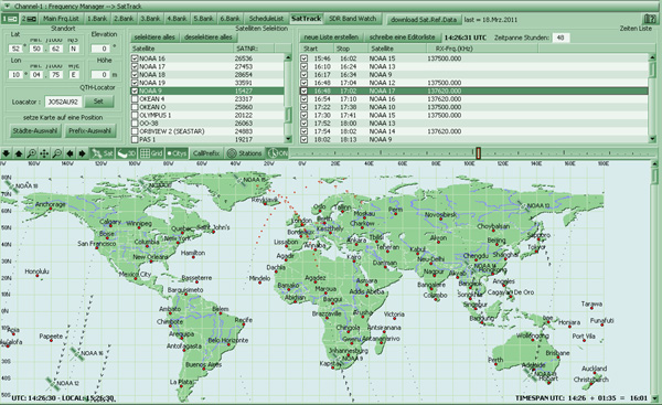
If you press the button “SatTrack” the BONITO Sat tracking will open. If you want to work with satellite faxes direct from satellites use SatFax. You will have to know where a satellite is and when it is able to be received. Therefore, you will need some reference data which you can update with button "download Sat.Ref.Data". The most important file is named ‘Satdata.2li’ and is located in the Data folder. You should update this file regularly. The updates are found on the Internet and are called Keppler elements. The entries for the satellite basic elements are located in the main frequency list. Only the numbers will be saved to make an update possible.
To determine the times when you can receive a satellite, the details of your location (QTH) are required. Enter in the section of the Observer Point your position. If you do not know where exactly is your geographic location, then click "SET" and point your mouse in the world map at the position where you are. For better orientation you can zoom into the map and show the cities. You can select different views like: coordinate system, 3D view of cities and the stations of the ScheduleList. You can change the City names by your self in Program directory at the folder CHART DATA and the file: cities.txt
Is a satellite in the list selected, it will be displayed in the map. The dots are to represent the flight paths. The red dots indicate which points can be seen from the satellite and which was seen.
If the clock is activated (ON), you can slide the time slider forward or backward and see the selected Satellites moving on the Map. The time is displayed in the bottom status bar as TIME SPAN.
You can create a timer List by clicking "create a new
List" In the right list, a list will be generated when which satellite
would be receivable for you. You can check or uncheck the desired
satellite time entrees. Note! Be careful of overlapping times and change
them if necessary. If you click on "write a list editor, an editor will
appear in the text of the list will be made available for your own
purposes.
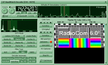
!!! This program part is only available if an SDR is installed or if "IF-Input" is enabled in the RadioCom Setup!!!
Software defined radios are very popular and are highly praised in the magazines. To take the advantage of the strengths of these devices Bonito invented the "Bonito BandWatch" in 2008. Bonito implement SDR Radios in that way that the owner really can use his SDR. Expensive "Virtual Audio Cable " or "Professional Demodulator" are therefore no longer necessary.
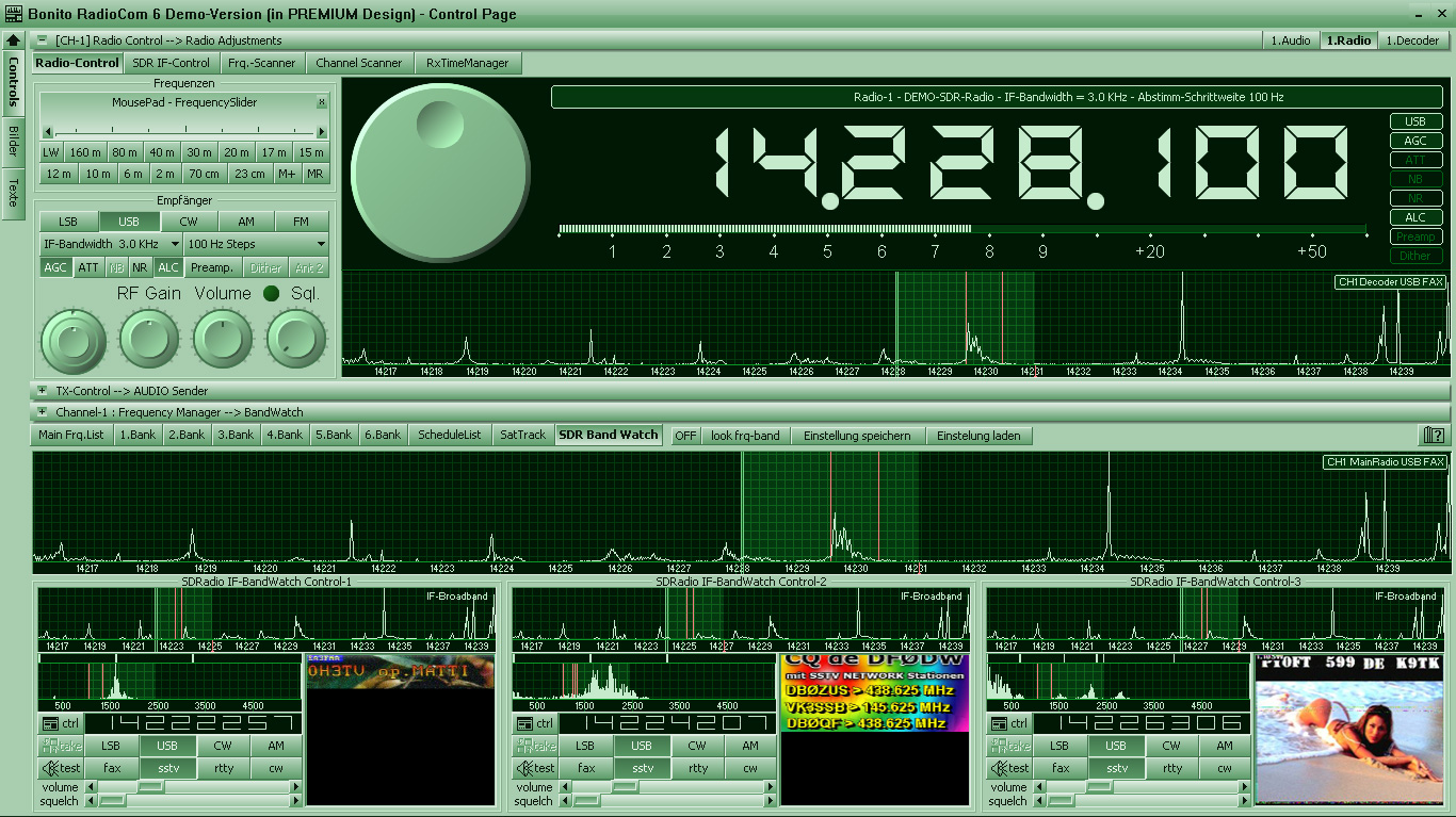
The new Bonito BandWatch® (Virtual Receivers) gives you the feeling to have more than only one radio. In the upper part of the BandWatch is the IF spectrum, that depending on the SDR can have a maximum bandwidth of 192 kHz at the Moment.
Each of the 4 BandWatch-Controls can have a different modulation and decoder. You can receive for example 4 different SSTV Images simultaneous.
The newly developed Bonito BandWatch (Virtual Receivers) gives you the feeling of owning not only one radio but using four to five radios at the same time. In the upper part of the bandwatch you have displayed an IF- spectrum which can be up to 192 kHz wide depending on the receiver. On this IF-Band, you see the filter, which is used for the main decoder in MidControl. Under it, you can find up to four BandWatches depending on the configuration. Each of the BandWatches is a virtual receiver, which can separately be tuned to a different frequency, different type of modulation or another decoder. Starting with an IF-frequency of 12 KHz e.g., you can receive four SSTV-pictures simultaneously. This function and the various possibilities are explained in Working with a software-defined radio (SDR).
|
Chapter
8.1 |
![]()
The main window includes the most
important control elements for controlling the radio. You should become
very familiar with these functions. The offered functions are different
from Radio to Radio and some Radios having more functions available in
the Protocol as others have. (NOTE: Your radio may not support/have all
functions!). On some Radios (Kenwood TS2000/TS480, Yaesu with Auto Info
(AI) like FT-450, 2000, 5000, 9000...) you have the possibility to tune
Frequencies on the Radio and it will change in the Software too.
Frequencies can be entered or dialed up and down by clicking the tuning
knob on the left side for down or the right side for up. The step size
is determined from a drop down menu when you click the button.
The NB button (NOISE BLANKER) will help eliminate static and
crackling noises.
With AGC, you can help stabilize the incoming signal if the
station strength is not constant. The signal strength(s) can be observed
on the scale at the upper left of the screen. If a signal is above S7
you can use the ATT button (Attenuation). This attenuates the antenna
input signal level if the signal is too strong and the receiver is
experiencing distortion.
The USB, LSB, CW, AM, FM, and WFM are standard modes. For
most digital modes you should use USB with an IF bandwidth of 3 kHz. AM
is used for normal radio stations on shortwave where 6 kHz bandwidth is
still used. However, there is a growing trend for some shortwave
broadcasters to use USB, and some experimentation will be necessary. Air
traffic stations use 15 kHz on frequencies from 108 to 138 MHz, and
numerous SSB channels across the HF spectrum.
Different modes can be activated or deactivated by the program,
depending on the radio you are using. SQL is the squelch, which reduces
interference when there is no signal being received. VOL is the
volume control. It controls the volume function on the soundcard, not
the radio.
The band selectors 80m - 23cm switch to a frequency within the desired
band that is generally or historically used for the currently-selected
decoder mode of operation (e.g. RTTY, CW, PSK, FAX, SSTV).
In the field MousePad - FrequencySlider you can click and hold the
mouse-button and then slide it to the left or right for fine adjustment.
Depending upon position, the frequency change will be either lower or
higher in direct proportion to the position thereof. Clicking the
switching box X increases the frequency adjustment by a factor of 100.
|
Mouse wheel Function |
 |
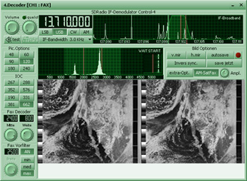
!!! This program part is only available if an SDR is installed or if "IF-Input" is enabled in the RadioCom Setup!!!
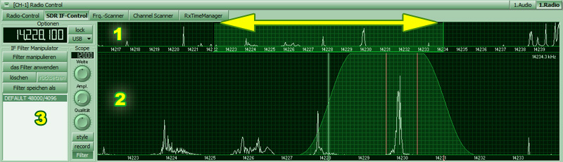
In the SDR IF-Control, the
IF-Filters and modulations can be designed with default filters or the
mouse and they can also be stored. An IF –recorder (record) is also
integrated and you can change the design of the display (Style) as
desired.
In the upper part (1) of the
display, you see the complete IF-band. Depending on the radio, it is up
to 192 kHz wide. The light green shaded area is variable and this
section is shown enlarged in window 2. You can enlarge or shrink this
area with the mouse wheel or move it left or right with the left mouse
button pressed down.
The IF-Equalizer (2) enables you to
put several notch filters in one band filter or to create a filter curve
with any waviness and variable steepness with a 2-Hz resolution. Simply
draw your filter curve with intricate features and eliminate specific
interfering signals.
Area (3) adjusts itself to any
selection: Style, Record and Filter.
These features and options are explained in:
Working with a Software
Defined Radio (SDR)

To analyze the frequency bands and
channel occupancy the Frq. scanner is used. Pressing the start button
starts the scan. The last parameters set in the radio control panel will
be used. Only the frequency is changed. The extracted signal will be
displayed on the green 3D window as a single line after a full scan. The
audio or S Meter responses indicate signal acquisition. A signal event
occurs when a signal breaks through the squelch and the audio becomes
useable. Not all receivers have an adequate squelch control. That is why
our audio squelch (the control on the Audio Control panel) “Asql” is a
much better squelch. It evaluates the interference much more effectively
than just responding to signal strength. For better results you can
flatten the lines (Flat) and leave the line without a context out (Not
O). The scan process stops when the “Stop On Signal” has been pressed.
The maximum delay time can be controlled by the value set in “Rec Time”.
A value of zero (0) means the process is stopped until the signal is
off. You can record the audio signal with the “Rec on Signal” button. By
changing the values of start, stop and step and press the “Make New
List” button a new list of frequencies is created.
You select what frequencies you want by clicking the small box next to
it. If you want to skip a frequency, simply uncheck the box.
By stopping the scan process you will be able to find the events in the
‘Scan Event Menu’. The 3D event window (here in the FRQ Scan) you can
activate a channel by clicking a box that is located on this scale.
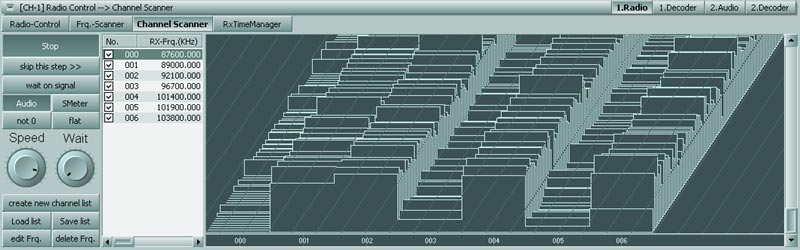
The channel scanner works similarly to the frequency scanner. The modes and IF settings are switched from a list. The list can be created by a drag and drop-down menu accessed by a right-hand mouse click in the list box. The entry can be changed as you like without modifying the main frequency list. By clicking "RUN" the scanner will start scanning the selected channels and shows you a spectrum as seen on the images.
|
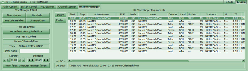
The "RxTimeManager"
regulates the time-controlled reception and switches at the
selected time to the appropriate frequency and operating mode. The start and stop times
to be changed in this dialog must be saved with the OK / apply
"button in RxTimeManager you see the following elements:
Create your own Timer |
|
|
Kapitel
7.2 |
|
Scopes and Analyzer |
Mid- und Top-Control 1./2. Audio
Audio Scopes
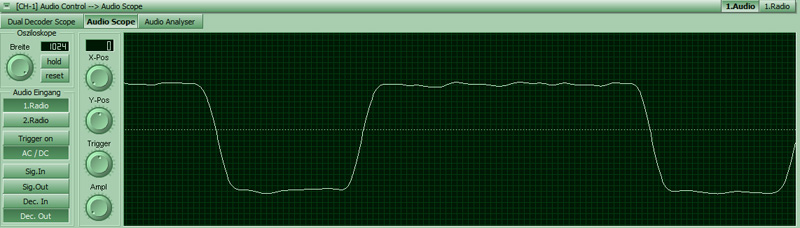
The audio scope is just like the Dual Recorder Scope, which will be explained further down. Only its screen is wider, it does not have a memory because it is only supposed to show live signals. The complete audio dialogue has four different scopes, which are very similar as far as the operation is concerned. Their usage, however, is meant for different analyses.
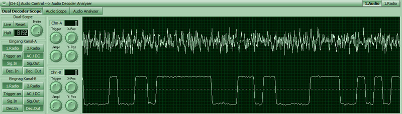
Dual Decoder Scope
The Dual Decode scope is intended to compare two channels. In
order to compare one signal to another they have to overlap. This
purpose is served by the Y-Pos and X-Pos But the X-Pos
only works when the width of the signal memory is considerably smaller
than 12288 samples. This memory has a size of 12 audio blocks. Every
block has 1024 samples, approx. 1 second of audio signal as memory. What
you see oscillating in the picture on the left, is the oldest block. The
last 1024 samples on the right are the live signal. To see only the live
signal, you have to tune the width to 1024 and the position to 11264.
Because this is inconvenient, there is the button live. For a reset, you
will find the button Reset . The button Stop stops the
memory and now you can analyze the signals in more detail.
Trigger starts the signal starting with a specific level. Every
time a signal line travels through this level, it will be shown with the
other signal being shown simultaneously. To trigger the other channel,
there is the button ‘Trigger On’. The amplitude is the height of
the signal and can be adjusted with the Ampl button with the
button on the left clicking into place and the automatic amplitude
control starting.
The other buttons are for the selection of the signal input, either from
the first or second radio. Sig.In means the direct soundcard input.
Sig Out means speaker out. Dec In represents the filter output.,
Dec.Out is the digital decode signal. AC/DC is used often
means alternating voltage and direct current voltage respectively.
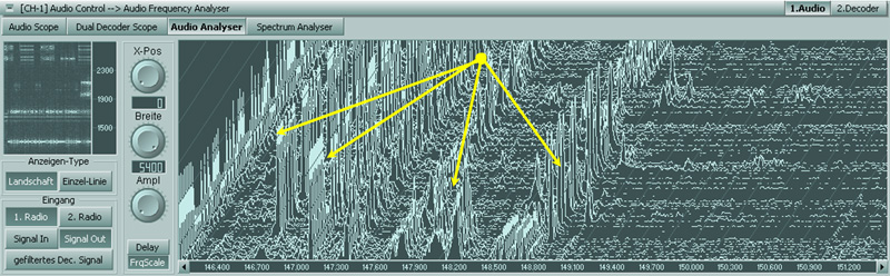
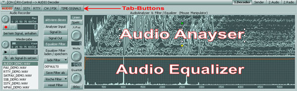
Audio Analyzer
the Audio Analyzer is meant for tuning the radio. There is a
small analyzer in every decoder. The dials and meters can control the
frequency of the radio. This can be done by clicking, dragging and
rotating the mouse wheel. The upper picture shows a single line
presentation while operating RTTY and so it has a XY-scope for
fine-tuning. The lower picture shows a landscape presentation. If there
is no RTTY operation, there will be a frequency spectrum instead of the
XY scope.
Tuning is a special chapter and will be explained on the following pages. That is why there is for now only a general description of the additional tuning of the radio frequencies and the filters. Not every analyzer can have a control function. It is only possible, where it makes sense.
If you double click on an
analyzer, the frequency will jump into the middle of the filter. That
means: double click on a clear peak in the display window and the signal
will jump in the middle of the filter because the appropriate frequency
offset will be controlled. The operations depend on the radio and the
decoder settings respectively.
You can also use the drag & drop method by clicking on the peak, keep
the mouse button depressed and drag the mouse to where you want to have
it located. That does not have to be the middle of the filter. Maybe an
indirect controlling of the radio is intended, if you simply drag to the
right or to the left and then drop it. Then rotate the mouse wheel to
correct the frequency so that that the peak will be in the filter.
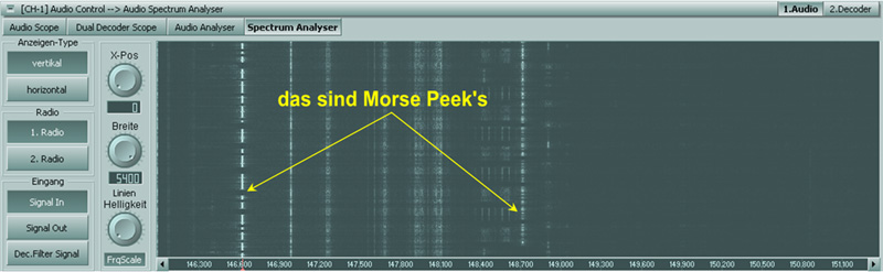
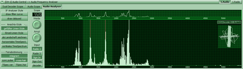
With CW or PSK, the frequency
control is not especially effective. With CW/PSK the audio spectrum
is state of the art. Here you put the filter on the peak. That means, if
you click on a peak in the spectrum, the filter middle frequency will be
put on the peak, whereas the radio frequency remains unchanged. Rotating
the mouse wheel or drag & drop has no effect in the spectrum. You will
recognize Morse peaks by their interruptions – they ‘stammer’ so to
speak. To easier recognize the peaks there is a button ‘Line
Brightness’. This control has an automatic brightness function, if
it is locked in the far left position.
The tuning of the CW decoder by Audio Spectrum is necessary
because the QSOs are often so short, that tuning would take too long and
as a result parts of the QSO would get lost. The QSO partners are often
on different frequencies, however. Therefore, the decoders can open a
small sub-window (Extra Decoder), where a different frequency can be
tuned in order to follow the complete QSO.
Working with the Audio Spectrum, you will only tune the filter. That is
why the radio frequency is controlled by the < > Buttons of this
scale (see image below) or by Mouse Wheel.

If you point the mouse to the red
mark on the filter, the pointer changes to a West/East arrow. This is
meant to indicate that you can move the filter by drag & drop. There
will be a long red line in the spectrum for better orientation. The
mouse wheel controls the radio frequency. If you keep the Ctrl key
depressed, the tuning of the mouse wheel will become more sensitive by a
factor of 10.
In the dialogue ‘Audio spectrum’, you can change the lettering of the
dial to the actual radio frequency. This is done with the button
FrqScale. A dial with radio frequencies has two so called
Step-Buttons on both corners on the right and left. These two buttons
control the radio frequency according to set tuning steps of the radio
|
Kapitel
8 |

All decoders can be activated by
right clicking on one of the tab buttons.
With the Audio Decoder, you can design specific audio filters and
record audio signals and listen to them. Additionally, you can turn on
some features, which affect the decoder. It is not necessary for the
Audio Decoder to be active, because it is never turned off. The
activation simply turns off the other decoders. The Audio Controls
should be set to Audio Wave because the playback is achieved by the wave
output of the soundcard. You will find the usual buttons here: Play,
Stop, Loop and Record of the Audio-Recorder. These
buttons have so called Tooltips, which describe briefly, what they are
good for. They are the small-labeled flags, which appear when you point
the mouse to one of the buttons.
To record, you press the button Record. When you press the button
‘Stop if no Signal’ nothing will be recorded as long as the Audio
Squelch or the Radio Squelch is closed. For playback, you press the
button Play or double click an entry from the list. To stop the
playback, you press Play again. If you press ‘Stop’,
everything will be stopped until you press the button again. When
pressing the button Loop , the playback will be repeated continuously. A
playback can also be sent as an input signal to the decoder by pressing
the button "use as Signal-In"
The equalizer bandpass characteristic can be customized in a manner similar to how one would draw a simple picture with the mouse. Click anywhere, keep the button down and draw the desired curve of the filter. If you press the right button the position will be set to the maximum. The analyzer can be zoomed for precise editing. The filter characteristic depends on the filter control.
The control quality adjusts steplessly the smoothness of the filter from hard to soft. The button delay delays the equalizer display. The Audio Analyzer shows the signals as a landscape. This can be changed with the button "Spect" to an audio spectrum and can be set back with the "Lines" button. For a more detailed drawing of the filter curve zooming is possible. To do this, use the Control "width" and "X-Pos" for positioning within the 5512 Hz wide filter.
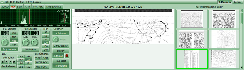
Weather maps are broadcast using „WeatherFax“. WeatherFax is the most frequently used way of broadcasting processed weather data. The fax decoder decodes facsimile broadcasts (weatherfax), which both are transmitted in the FM mode, as well as satellite pictures in the AM mode. Important are the frequencies and transmission times. The frequencies can be found in the frequency manager. The transmission times for the weather fax can found in the Schedule List. The satellite orbits in SatTrack.
|
ExtraDecoder By clicking the "ExtraDecoder" the SubDecoder can be opened for special purposes. This SubDecoder appliance assumes the currently set parameters of Faxdecoder, where they were set manually or by double clicking on an entry from the frequency manager set correctly. Normally you don not need to configure anything, because all parameters were already set with a double click on the Frequency. Image formats - Fax Module (IOC) |
|
|
Drum Speed RPM The drum rotation speed of a fax is denominated in revolutions per minute (rpm). A normal weather fax uses 120 rpm. Weather maps from Russia and Japan may come at varying speeds such as 60, 90 or 120 rpm. |
|
Shift & Center frequency Fax
Decoder
It is important to shift the tuning from high frequency tones to lower
frequency tones in order to avoid interference. This means you are
shifting the red markers in the frequency spectrum along the horizontal
scale.
Fax PreFilter
„Width“ is the spacing between the lowest and highest tone frequency of
a signal. That is the spacing between the two red markers in the
spectrum display. The filter should be the same width. Filter
adjustments that are narrower or wider may also improve the reception.
Start/Stop Frequencies
Start- and Stop frequencies are sounds played at the beginning and end
of an image. Normally there would be a 450 Hz tone for start and a 300
Hz tone for stop. After the start tone MeteoCom starts recording the fax
and saves it to the hard drive after the stop tone.
Fax tuning and Slant-Correction
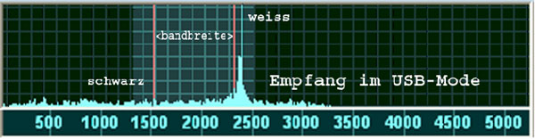
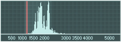
This is the display for tuning the tone frequency (also page 16). In most cases a fax signal USB shows more activity on the right side that degrades towards the left end of the bandwidth (red marker). In order to receive good, clear images, the main signal activity bar should always be just in front of the red marker. In case of distortion you can shift the IF to the left or right, narrow the bandwidth or manipulate the filter.
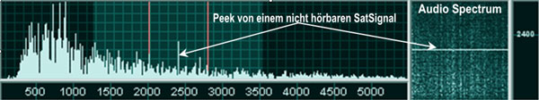
Using the small audio spectrum display, it is possible to detect weak signals that you do not hear - especially in the AM SatFax.
|
Slant correction |
 |
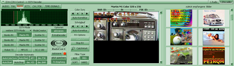
The SSTV decoder decodes the transmission of ham radio amateurs. The radio amateurs often send on different frequencies as the corresponding QSO partner. This makes it sometimes difficult to tune the frequency of the other partner.
|
ExtraDecoder
The "Save now" button saves the image now, which is
located in the reception window. If the button activates auto
save, on reaching the lower edge of the image stored the image
independently. |
 |
SSTV-FREQ:
These buttons change the radio to different preset frequencies in
the program.
AVIS:
There is a start signal in a SSTV signal. This automatically starts
the reception of a picture and saves it at the end of the transmission.
This usually always works. You will have to press Receive to start
reception. Autosync will try to synchronize the picture. Pressing the
‘Autosync’ button will resynchronize the picture until the colors are
right. Then you can correct the picture with ‘ColorSync’ placing it the
proper position.
SSTV-Modi
There are many different operation modes are currently available:
| Martin: |
M1, M2, M3, M4 (COL) HQ1+HQ2 in preparation |
|
| Robot: | R8, R12, R24, R36 (BW) R12, R24, R36, R72 (COL) | |
| Scottie: |
S1, S2; S3; S4 (COL) DX1+DX2 in preparation |
|
| Wrase: |
SC1 8, SC1 16, SC16sq; SC1 32 (BW) SC1
24, SC1 48, SC1 96 (COL) SC2 30, SC2 60, SC 120, SC240 (COL) |
|
| Bonito: |
B1 320x256, B2 320x256, B3 320x128, B4 320x128 (all Color) C1 320x256, C2 320x256 COL FC1 BW+COL 320x256, FC2 BW+COL 320x256 |
|
|
MM: |
MP 73, MP 115; MP 140, MP 175 (COL) MR 73, MR 90, MR 115, MR 140, MR175 (COL) ML 180, ML 240, ML 280, ML320 (COL) MP 73-N, MP110-N, MP140-N (COL) MC 110-N, MC 140-N, MC 180-N (COL) |
|
| PD: | in preparation | |
| Pasokon | in preparation | |
| ATV | in preparation | |
It is planned to add more modes. This will be possible via online
update.
Please use at certain intervals, the update function in
Setup.
SSTV tuning and SLANT (Skew) Correction:
|
Tuning: |
 |
|
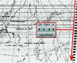
SSTV SLANT Correction: You can correct the slant of a picture by using the ‘10x or 1x’ slant buttons. You should press and hold the button until the picture is straight. The correction factor is either 10 pixels or 1 pixel per single click of the button. Pressing and holding the button will provide a quicker correction. The ‘Save This Now’ button will save the picture in the receiver window. The ‘AutoSave’ button will save the picture when the lower edge is reached. You can load and print the picture. Color Sync |
 |
|
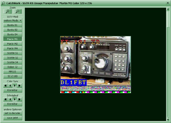
Catch Work ZOOM: minimizes / maximizes the picture SSTV-Modes: Here you can select the various modes which influence the segment. This is ideal in case the mode was not recognized automatically. ColorSync:
When you press ColorSync, the picture will be
re-synchronized. Press the button until the color of the picture
is as desired. |
 |
|
Slant correction: Here you can correct the slant. You have to press the ‘Slant’ button until the picture is received straight. Press the button which points opposite the slant. With the button ‘10x’you correct the picture tentatively and with the button ‘1x’ you fine-tune it. This won’t be possible before you receive a picture. |
|
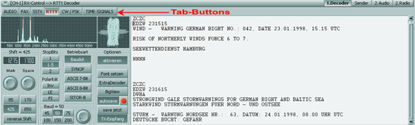
In order to decode RTTY, you first have to activate the decoder by
depressing the button ‘activate’ by right-clicking the tab button
|
If you depress ‘Extra Decoder’, a sub-decoder
will open. With the button ‘Select Font’ you can change the font
and the color of the text. If the button ‘autosave’ is
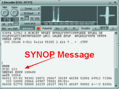
depressed, a paragraph will be ….when receiving ZCZC (the LED
will be red) and when receiving NNNN (no LED), this paragraph
will be saved as a text file. With ‘Save now’, the complete text
will be saved in the buffer. |
 |
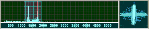
Audio Analyzer und XY-Scope
This is a display showing all tone frequencies up to 5500 Hz
from left to right. The height corresponds with the volume (amplitude).
The amplitude is dependent upon the tone’s frequency. You should always
try to find the tone frequency yielding the strongest amplitude. There
are precise technical standards which specify at which tone a signal is
tuned properly. In real life, however, all this depends on the filters
used in your radio. The filter curves are not always the way they should
be. This means that the frequency list is always a theoretical tool and
not adapted to your specific radio.
Adjust Audio RTTY
Usually, the tuning displays process the tones received by
the radio in such way that you can observe the way the radio tunes the
signal. These displays should help you understand how the tuning process
works. As a first test it may be useful to just turn the main tuning
knob of your radio to acquaint yourself with it. If, later on, you want
to tune more precisely, you need to use the „Receiver-Control“ because
eventually your radio doesn’t report to RadioCom when you tune your
radio manually.
Make sure that both amplitudes are lined up exactly with the red lines. The spacing between the red lines corresponds with the band width (shift). The position on the scale is the tone’s frequency or pitch. The height shows the volume. This picture shows an RTTY signal with two different tones. One for “mark” and one for “space”. Both tones should be lined up with the vertical red lines. In case of a Fax signal, the bandwidth is usually greater, meaning that the two vertical lines are further apart and there is almost always only one bar at the red line on the right.
| Using the „Receiver-Control“ tune the radio in such way that both signal amplitudes line up with the red markers or the lines of the tuning cross are exactly perpendicular. |
 |
X/Y-Scope (Tuning Display)
On the preceding page a RTTY signal was used as an example whose
adjustment is now displayed on the X/Y display. Get the signal between
the red lines (Shift) by using the frequency spectrum. Then get the
cross. If that will not work, you can play a little bit with the shift.
If the shift is correct, the bars will be placed somewhat orthogonally
on top of each other. To function properly make sure the crossbars
remain mutually perpendicular.
 |
 |
| 85 Hz Bandwidth | 425 Hz Bandwidth |
RTTY Modes
Normally, you do not have to do anything, if you double-clicked a
frequency entry in the frequency manager. All parameters will be set
correctly.
Baudot and SYNOP
Both of them are asynchronous modes which are used by press agencies,
weather services and ham radio operators. SYNOP transmissions are
weather reports which start with ZCZC, have a large number of figures in
groups of five each and end with NNNN. RadioCom decodes these messages
and shows them in German. The SYNOP database is updated regularly on the
MeteoServer of Bonito and you can update this program yourself.
Sitor-B und Navtex
Sitor B is a synchronous mode which is different than Baudot, but it has
the same logic. It has properties which make it considerably more
interference-free. Navtex uses Sitor with 100 Baud and inverse.
Adjusting the Baudrate
The speed of the bits in a telefax is called baudrate. The baudrate most
used is 50 bauds , but there are messages which are transmitted with 75
bauds and very rarely with 100 bauds.
The shift is the space between the two sounds which signal the bit state
of a RTTY-Bytes
Polarity
If the message and the decoding makes no sense, you should try to change
the polarity to improve readability. Navtex, for example, always
transmits inverse. But unfeasibility can also have other reasons, for
example when the text contains a wrong character which makes the decoder
only write figures and letters. In this case, try and find out, if the
LE-mode makes the letters intelligible. Only depress FI in the opposite
case, when the groups if five numerals in SYNOP appear as groups of
letters.
Stopbits
Basically, Baudette only has 1.5 stop bits. There have transmissions,
however, with two stop bits. This is why you have this button to adjust
the stop bits. With SITOR you don not have to adjust anything here
because this mode has not stop bits.
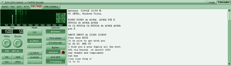
To receive CW and PSK you have to activate the
decoder by depressing the button ‘activate’. With these very narrowband
modes it is customary zoo use one or several sub decoders. Many signals
are adjacent to each other in one band and the multi-decoder will be of
good use. With the button ‘extra decoder’ you can open any number of
decoders. With ‘Select Font’ you can change the colour and the font of
the text window. If the button ‘auto save’ is activated, a paragraph
will be highlighted when receiving ZCZC (LED is red) and when receiving
NNNN (no LED) this paragraph will be saved as a text file. When
depressing the button ‘Save now’, the complete text will be saved.
|
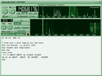
If you double-click the text window or
depress the button ‘BIG View’, a large text-editor-window will
open. If you want to decode the message while being transmitted,
press the button ‘TX-receive’. In contrast to a RTTY decoder you
do not put the radio frequency into the filter with the audio
analyser, but you put the filter on the Morse peak. The easiest
way to adjust a Morse signal is with ‘Audio Spectrum’ On page
20, you will find a detailed description of this spectrum. |
 |
| With the button ‘FRQscale Style, you put the lettering of the dial on the actual radio frequency. The width of the filter can be adjusted from 10-540 Hz with the button ‘Width’ The buttons ‘min’, ‘med’, ‘max’ and ‘open are pre-adjusted filter widths. If the button CW is activated, Morse code will be decoded. The other two buttons B_PSK 31’ and Q_PSK 31 activate the decoding of PSK | |
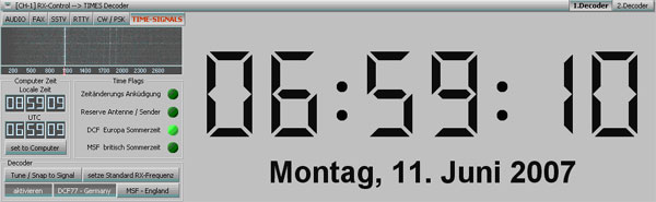
This decoder decodes time signals. To receive time
signals you have to activate the decoder with the button ‘activate’ All
decoder can also be activated by right-clicking on one of the tab
buttons.
At present, two kinds of time signals can be decoded:
DCF 77 PTB on long wave 77.5. kHz (Germany)
MSF NPL Teddington on long wave 60.0 kHz (UK)
There are plans to realize other modes which will be published per
updates. So, please, have a regular look at our update service.
Adjusting the frequency is automatic, but can also be done manually with
the audio spectrum. Similar to the CW-decoder, you place the filter on
the peak of the time signal and not the radio frequency. A detailed
description of this spectrum display can be found in this Manual.
Place the filter exactly on the peak of the time signal. This filter is
a static one with a width of 40 kHz. By clicking the peak in the audio
spectrum, the filter will be placed exactly where you click. You can
also move the small red line on the dial with drag & drop. This dial is
always 3000 Hz wide and will not tune the radio frequency (?FL)
If the signal is not exactly on the filter, depress the button
‘Tune/Snap to signal’ The signal will be readjusted. If no signal can be
detected, no filter can be placed
If you depress the button ‘Set standard Rx-frequency, the receiving
frequency will be tuned to on the radio in accordance with the mode
which was selected with the button DCF 77-Germany or MSF (UK)
If the time received is correct, the watch will be highlighted and you
can depress the button ‘Set to Computer’ to synchronize it with the time
of the PC.
In the field time flags, there are LEDs, which indicate the current
operating state. In the picture above, you see that daylight savings
time is active.
|
Kapitel
9 |
|
Audio Encoder (TX) |
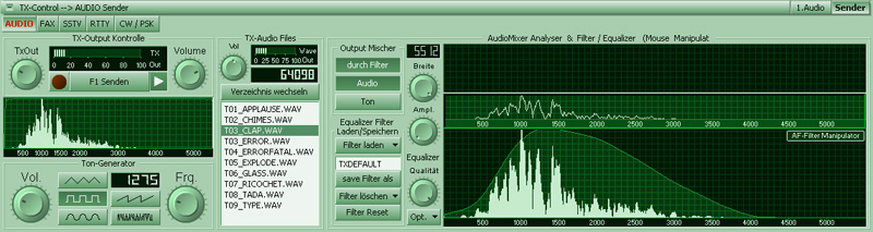
This is the encoder-dialogue for transmitting audio signals of any kind. To transmit Audio, the encoder must be activated. The encoder is activated by right-clicking the mouse on one of the tab buttons. Should the encoder not be active, it will automatically be activated by pressing the transmit button F1 or the button F1 Transmit.
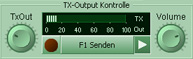
| The control Tx Out controls the volume of the output signal, which will be sent via the Line-Out of the computer. The button ‘Volume’ controls the volume of the loudspeaker. The LED is lit, if the transmitter is active. You can transmit audio files and you can test a transmitter with the sound generator. |
 |
In the group field of the sound generator, there is
a control button ‘Frq’ for the generated audio frequency and a button
‘Vol’ which controls the volume (amplitude) which is sent to
the mixer. The five smaller buttons determine the characteristics of the
sound: Triangle
![]() ,
Rectangle
,
Rectangle
![]() ,
Sinus
,
Sinus
![]() ,
Saw tooth
,
Saw tooth
![]() ,
Signal Noise
,
Signal Noise
![]() .
.
You can also mix the audios and pass them through a
filter to suppress or amplify specific harmonics. On occasion, this can
be very useful to find a mismatch of the transmitter.
To better determine the quality of the audio signals an audio scope and
an equalizer-filter are integrated. You can find more details on the
page ‘Audio Decoder’
The control button ‘Width’ determines the width of the display (in
sample). The analyser in ‘Filter Equalizer’ shows you the harmonics,
which can be best seen with a saw tooth signal. You will see one large,
long peak followed by several smaller ones (to the left, and also to the
right next to the large ones). In contrast, a sine sound will not
produce harmonics.
Here you see a complete screen with the SSTV-Encoder in the middle for transmitting SSTV pictures. In order to transmit SSTV the encoder has to be activated. The three tab buttons in the header control each a separate sub dialog.
|
Transmit List
If you want to transmit it, double click on the picture. A text editor will appear from where the picture which you want to send will stored in a set. When transmitting each picture will be loaded from this set into the transmit window until the set has been completely transmitted. These pictures then will be saved to the Log Directory where you can view them under 'Pictures Sent'
|
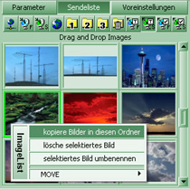 |
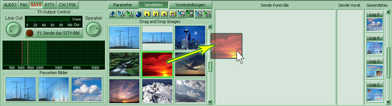
You can also select the picture which you want to send by selecting it with the mouse and move it into the transmit window by dragging and dropping it there. You can move the pictures anywhere you want. You just have to click on the picture and move the mouse. If you drop the picture in any directory ,the picture will be moved there. In the same manner you can save you favorite templates in any one of the three favorite windows or in the transmit window.
|
SSTV Picture Editor |
 |
|
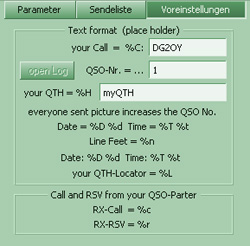
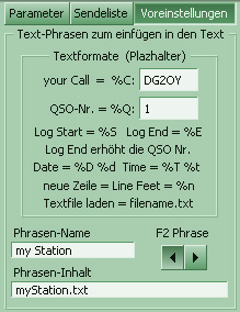
With the sub dialog Preselections you can determine what is in the header and the footer. You can also choose a color of your liking. The text can have a placeholder text which can be marked by '%'. '%D' stands for the date with the current year and month, whereas '%d' is the same but shorter. The seconds will be marked as '%T', '%t' has no seconds. '%C' stands for your call sign and '%Q' for the number of the QSO. Each successful transmission will be added automatically. |
 |
|
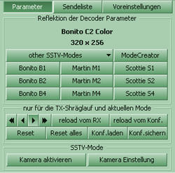
In the sub dialog Parameters there are exclusively parameters for transmitting. Here you can choose the desired mode. Also the slant of the transmitter can be controlled just like in the decoder. Normally the values are the same for both. So you can reload them with 'Reload vom Rx' to have a good basis for the fine tuning of the transmitter. |
|
|
WebCam-Support |
|
| If that worked out, activate your camera with 'activate Camera'. In the section 'Favorite Pictures' you should see a picture of the webcam. If you want to transmit this picture, simply double click it and proceed as above | |

|
Fax Encoder TX |

Here you see a complete screen with the Fax-encoder
in the middle field (Mid Control) for the transmitting of Fax-pictures.
To send Fax, the encoder has to be activated. Each of the three tab
buttons at the very top activates a new separate Sub Dialogue. These
options have already been described in the SSTV section and can be
reviewed there.
In the sub dialogue are your drafts, which are in the folder
programs/Bonito RC60/Images/TXFAX. All transmitted FAX are in the log
folder, which can be viewed under ‘Sent’
For FAX Images, the text editor is somewhat larger. The size of the header or footer is dependent on the selected resolution module. Often it is necessary to adjust the font to the resolution. Additionally, the FAX text editor can show the Fax picture in the original resolution. The operation is described in the SSTV chapter.

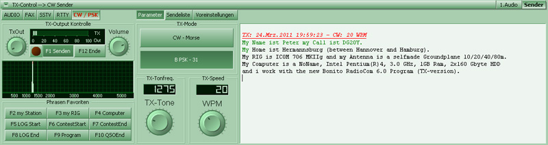
This is the RTTY encoder to transmit text
messages. To send text messages the encoder must be activated. Each of
the three tab buttons at the very top activates a new separate Sub
Dialogue. A text editor is used which is adjusted appropriately. The
green text has already been transmitted and cannot be edited. If there
are problems (it looks like no transmissions are possible), you depress
the end key on the key board and go to the end of the text. For further
text options, a context menu can be opened by right clicking the mouse
in the context menu.
In the group field ‘phrase favorites’ a button for the fast entry of
text phrases, which can also be inserted with the F2-F10 keys. F1 is for
transmitting and F12 ends the transmission after the last character.
While copying in the RTTY decoder your text will be green. The text of
your qso partner remains black.
There is display of the decoder parameters in
the sub dialogue ‘Parameter’. The button ‘Activate Idle Mode’
transmits a special synchronization signal when the transmitter is
idling.
|
Preselections
Phrases |
 |
This is the CW/PSK encoder for the transmission of
texts. To send text messages, the encoder must be activated. The three
tab buttons at the very top turn on a separate SubDialogue each. A
suitable text editor is made use of. The text in green has already been
transmitted and cannot be edited. If there are problems and it seems
like you cannot enter anything, depress the end key of the keyboard and
go to the end of the text. For additional text options a context menu in
the text window can be opened by right-clicking the mouse.
In the group field ‘Phrase Favourites’ you see a button for the quick
entering of text phrases, which can also be entered with the F2 – F10
buttons. F! is for ‘transmit’ and F12 ends the transmission. While
copying in the CW/PSK decoder your text is written in green, your QSO
partners stays black
|
Preselections
Phrases |
|
|
Kapitel
10 |
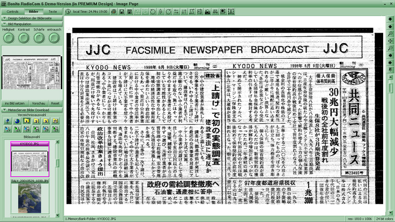
|
This is where the storage of the various images is,
e.g. Weather maps, Satellite images, saved and deleted images. Zoom Slider: Below the navigation bar there
is a slider which makes zooming even easier. Point your mouse to your
position and click on the right mouse button. A context menu will open.
Select “Set fix point”. If you now use the zoom slider, you will always
zoom back to the selected position. Even when you are zooming into other
areas you simply need to touch the slider to get back to where you were
before. Directory and Source selection
|
|
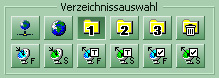
There are seven icons that correspond to seven folders for handling various types of images. From left to right, there are three receiving folders – the Download Folder for various satellite images, the Fax Folder for receiving the radiofax images and the Download Folder for the satellite weather images. The next three icons are for three containers, “banks”, where you may store the received images to protect them from being deleted by the “automatic deleting procedure”. Here you may sort and archive images that you want to keep.
If you would like to archive images, simply drag and drop them to one of the “banks”. The “automatic deleting routine” will not delete images saved there.
The last icon represents the “trash bin” – a folder where the images are kept only until the automatic deletion removes them for good. To move an image from one folder to another, go to the source folder then select the image and drag it to the destination folder. If you drag an image by mistake into the “trash bin” folder, you can just select the trash folder, find the image and drag it back to the desired folder. The images from the trash folder are not deleted immediately. The automatic deletion will remove them after eight days, therefore there is a chance to recover some of the images moved there by mistake.
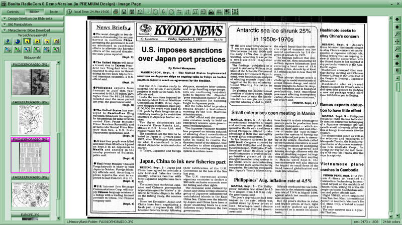
„Images selection“ contains images sorted by date. Double-clicking an image will bring it up in the large window on the right where it can be viewed and edited.
|
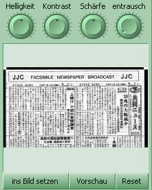
Image manipulation Contours, Soften, Sharpen, Brightness Synchronize |
|
|
|
| Use this function when the received
image is skewed. Click on the upper edge of the image and draw a line along the skewed edge of the image. Clicking again will correct the image. |
|
|
| Click on the button. Then click your left mouse button
and draw a rectangle around the area you want to crop.
Release the mouse button. You can now still manipulate the
area by clicking on the edges and pulling them to a
different position. Clicking the right mouse button will
finalize the crop. |
|
|
|
You can receive a fax image in LSB reverse. You do that to improve image
quality. The image will be received inverted. This function will revert
the image to normal. |
|
|
|
If the image is arranged wrongly you can rotate it by clicking on the
appropriate button; 90 degrees anti-clockwise, 180 degrees or 90 degrees
clockwise, respectively. |
|
|
| If a fax has been recorded with a wrong module or at the wrong speed, it can be turned into a readable form by clicking on this button. You will be prompted with a dialog box to provide the appropriate parameters. |
|
Image Internet Download With RadioCom 6 you have the capability to download Satellite Images to your Computer and have RadioCom automatically create animations. Since these pictures are not forecasts you can select the time frame for satellite pictures in the “load pictures for...” selection box If you press the split bar "MeteoServer Image
Download", the download manager appears. This allows you to download
satellite images from the Internet. With the Button "Start download..." the download starts. The downloaded raw data are processed into images that are stored in the "SAT folder" or in the "Animations folder". The images are from MeteoServer.net, which is operated by Bonito. It is the professional service - nautical, Meteorological Marine Service - which is used worldwide.
|
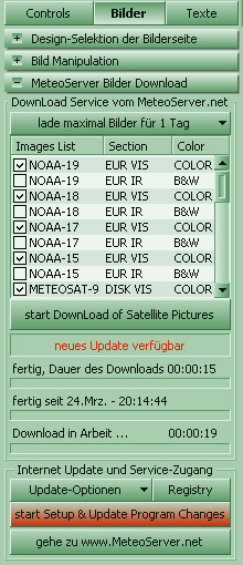 |
With RadioCom 6 you have the capability to download Satellite Images to
your Computer and have RadioCom automatically create animations. Since
these pictures are not forecasts you can select the time frame for
satellite pictures in the “load pictures for...” selection box. The
maximum amount is 72 hours. Select the desired pictures you want to
download in the “Image List”.
Printing
The printing is slightly different. There are 3 images exist from one
time: Vis, IR and WV, the 4th picture is a color combination.

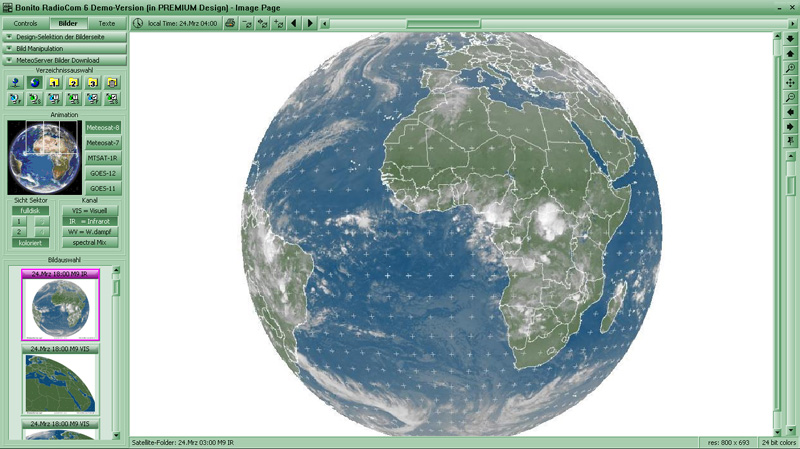
Animation Satellite Movie
This button:
![]() is
PLAY forward and this:
is
PLAY forward and this:
![]() back
wards .
back
wards .
With the buttons
![]() and
and
![]() sets the speed at which animations are played. The
speed is also dependent upon the processing speed of your PC. This
button
sets the speed at which animations are played. The
speed is also dependent upon the processing speed of your PC. This
button ![]() sets the speed back to standard.
sets the speed back to standard.
Switching local time to UTC/Clock
Weather data are always in UTC. To get a better overview of the forecast
you can switch to local time.
Time slider
By moving this slider to the left or right you can move data manually.

This is where all received text messages such as forecasts, warnings,
Navtex etc. are displayed. Texts belongs to certain areas will be stored
in the respective folders. Forecasts for the Mediterranean can only be
found in that folder. This makes finding the proper forecast much
easier.
ICON Bar: Text
The toolbar is certainly known to you by word processing programs.
We go through the various functions from left to right:

Print; Save, Save as..., Clear, F=Font,
Font Color, B=Bold, I=italic, U=underline
Left-; Mid-; right ranged; List
It may irritates you that the design has been reproduced here dark blue
instead of the usual representations in this manual.
Here's how you can change the color design.
|
(c) 2000-2013 BONITO Germany |
|
|
|
Web: www.bonito.net - www.hamradioshop.net - www.meteoserver.net - www.wetterinfoshop.de |